Installing And Configuring IDE / EIDE Devices
Configuring IDE is the usual interface for hard drives. The term IDE means that the drive has a built-in ontroller rather than a separate chip as part of the motherboard chipset.
Integrating the chip within the drive leaves manufacturers free to develop the technology of IDE devices without worrying about whether it will still be compatible with a chipset on a particular ' motherboard.
IDE drives are compatible with the ATA standard, this means you can install an old drive in a new system, and it should work. Installing a new IDE drive into an old PC may not be so successful.
The ATA standards have improved with time, each new version being given a new number ATA-1, ATA-2 and so on. EIDE devices were so named because, at the time, they supported the ATA-2 standard rather than the original AT standard. However, since then, all IDE devices now fall into this category, so the term EIDE is often lost, and you may just refer to Configuring IDE devices.
EIDE - Enhanced Integrated Drive Electronics
ATA-4 is of particular interest: it introduced a way of increasing data transfer speed called UltraDMA - or UltraATA. This allowed data transfer rates of 33 MB/sec. This improvement in data transfer rates continued, with ATA-5 taking it to 66 MB/sec, and ATA-6 reaching 100 MB/sec. The UltraDMA for the higher speeds (66 Mb/sec and 100 MB/sec) requires a double-width cable: 80 wires instead of the usual 40.
There are still only 40 pins to connect, but the other 40 wires act as spacers, reducing the EMI between the more important data-carrying wires. This reduction of noise means that data can be transmitted quickly without loss of integrity.
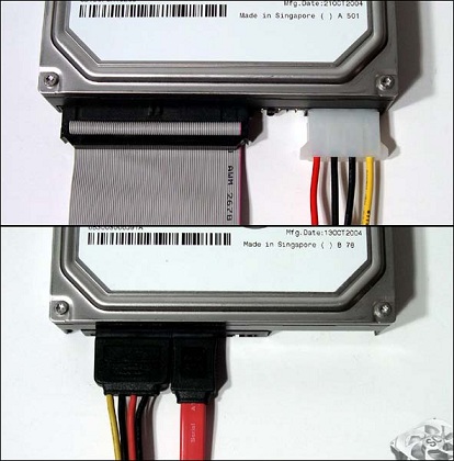
Therefore you can attach two devices on the one channel. However, there are two connectors on the motherboard so you can attach up to four devices, called the primary and secondary channels. The hard drive may be connected to the primary channel or IDE1 connector on the motherboard using an IDE 40-pin 80-conductor ribbon data cable. This is similar to the I cable and easily mistaken for it - but each conductor has a ground wire and hence there are 80 instead of 40 conductors.
If you use the wrong cable, the hard drive will not work properly. A CD drive - or another hard drive - can then be attached to the secondary channel or IDE2 connector on the motherboard using an IDE 40-pin 40-conductor ribbon data cable.
The CD drive is also attached via an audio cable. Audio cables are usually notchec to help you to plug them in the correct way. If you connect it the wrong way around, you may get no sound when you power up. Whatever drive you connect, there will also be a power cord to be connected to the PSU.
How to install IDE/EIDE devices
IDE devices include hard drives and CD-ROMS. This panel considers how to install a hard drive. Installing a hard drive is similar to installing a floppy drive except the cover does not need to be removed.
- Set the jumpers.
If you are installing a second drive, you will need to check the settings for the first drive; they will need changing - e.g. from single' to master'.
-
Put the drive into the bay. You may need to screw the drive into place, or there may be mounting rails that fasten to the side of the drive so that you can click the drive into place.
- Connect the drive to the motherboard using the ribbon cable. You need to select the correct cable: 40-wire or 80-wire, depending on the specification of the hard drive. They are the same width and both fit into the same connector. The cable has two ends: one "for the motherboard and one for the drive. The.-e is also a connector midway which you
Configuring IDE for Primary Vs Secondary On The Motherboard
- Open up pc case
- Set/check jumpers
- Put drive into bay
- Connect drive to motherboard
- Connect drive to PSU
- Close PC case
- Restart PC and check BIOS recognises drive
- partion drive
- format drive.
See Also...
Site's Navigation
 Subscribe To This Site


Copyright 2010-2016 Custom-Build-Computers.com | Faisal Opare | All rights reserved.