Motherboard Diagram With Labels
Motherboard diagram with labels. A motherboard is one of the most confusing components and simply looking at it can leave you completely dazed. This is because it has numerous hardware parts, power cables and connectors.
In addition to this, it also comes with a panel of various I/O connectors, drive connectors, memory slots, power delivery units, power in-puts and chipset. As such, it is easy for people to get confused and this is where the motherboard diagram comes in handy.
This is often labeled and it highlights the varying components of the board as well as providing a short description on how these parts are used.
Guidelines for Motherboard Diagram With Labels
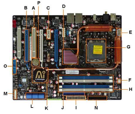
A. -PCI Slot, which can be, used for different types cards.
B. PCI-E slot used for graphics card
C. PCI 1X slot used for Ethernet and sound cards
D. Northbridge for communication
E. Pin power connection which deliver power supply to the motherboard
F. CPU fan
G. Socket where the CPU is plugged in
H. Memory clots for the RAM
I. Power Connector, which is the main power supply connector.
J. IDE connector, which connects your hard drives and the DVD/CD drives.
K. Southbridge, which controls other components of the motherboard
L. SATA connection, which are used for hard drives.
M. Front panel connection, which are used for lights, hard drive and power on activities.
N. FDD connection which is for your floppy disk
O. External connections which are used for plugging in external USB
P. CMOS battery, which is for holding your battery.
All these connectors would be almost impossible to understand without a motherboard diagram and it is for this reason that it is considered important. With this, it becomes easy for first time users of a motherboard to understand how they can use the same. It makes it easy to understand the role played by each component and makes it easy for users to enjoy the benefits associated with use of a motherboard.
See Also...
Site's Navigation
 Subscribe To This Site


Copyright 2010-2016 Custom-Build-Computers.com | Faisal Opare | All rights reserved.