Computer Assembling Tips Guide
One can follow this easy basic steps to do computer assembling. As PC builder or not needs to be comfortable with taking apart a computer and putting it back together, even if you have not build a PC before and is your first time dont worry, this site will guide you.
In most situations, the essential tools you'll need for the Computer assembling job are a ground bracelet, a Phillips-head screwdriver, a flat-head screwdriver, paper, and pen.
As you work inside a computer, be sure to use a ground bracelet, the safety precautions in the chapter, and the guidelines in the following list.
- If you are starting your Computer Assembling with a working computer, enter CMOS setup and write down any customized settings you have made so that, in the event you must return CMOS to its default settings, you can restore the customized settings. Back up any important data on the hard drive.
- Power down the system and unplug it. Unplug the monitor, mouse, keyboard, and any other peripherals or cables attached and move them out of your way.
- Put the computer on a table with plenty of room. Have a plastic bag or cup handy to hold screws. When you reassemble the PC, you will need to insert the same screws in the same holes. This is especially important with the hard drive, because screws that are too long can puncture the hard drive housing.
- Sometimes I think figuring out how to open a computer case is the most difficult part of disassembling.
- To remove the cover of your PC, do the following
- Many newer cases require you to remove the faceplate on the front of the case first.
- Other cases require you to remove a side panel first, and really older cases require you to first remove the entire sides and top as a single unit.
- Study your case for the correct approach.
- If you find screws on the rear of the case along the edges start with removing these screws.
For A Desktop Case Or Tower Case
For tower Case locate and remove the screws on the back of the case. For a desktop case, look for the screws in each corner and one in the top. Be careful not to unscrew any screws besides these. The other screws probably are holding the power supply in place.
- After you remove the cover screws, slide the cover forward and up to remove it from the case. Older tower cases also have the screws on the back. Look for screws in all four corners and down the sides. Remove the screws and then slide the cover back slightly before lifting it up to remove it.
Some tower cases have panels on either side of the case, held in place with screws on the back of the case. Remove the screws and slide each panel toward the rear, then lift it off the case.
- Newer cases require you to pop the front panel off the case before removing the side panels. Look for a lever on the bottom of the panel and hinges at the top.
Squeeze the lever to release the front panel and lift it off the case. Then remove a single screw and slide the side panel to the front and then off the case. Also, know that some case panels don't use screws; these side panels simply pop up and out with a little prying and pulling.
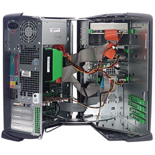
- Computer Assembling tips for tower cases, If you're working on a tower case, lay it on its side so the motherboard is on the bottom. If you plan to remove several components, draw a diagram of all cable connections, DIP switch settings, and jumper settings.
You might need the cable connection diagram to help you reassemble. If you want, use a felt-tip marker to make a mark across components, to indicate a cable connection, board placement, motherboard orientation, speaker connection, brackets, and so on, so that you can simply line up the marks when you reassemble.
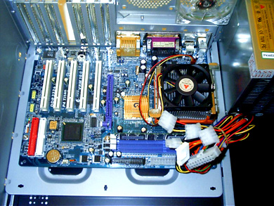
- Drives are connected to the motherboard with ribbon cables or thinner serial ATA cables. Before removing any ribbon cables, look for a red color or stripe down one side of each cable.
This edge color marks this side of the cable as pin 1. Look on the board or drive that the cable is attached to. You should see that pin 1 or pin 2 is clearly marked. However, some boards mark pin 34 or pin 40.
For these boards, pin 1 is on the other side of the connector. Also know that some boards and drives don't mark the pins, but rather have a notch in the connector so that a notched ribbon cable can only be inserted in one direction.
See Also...
Site's Navigation
 Subscribe To This Site


Copyright 2010-2016 Custom-Build-Computers.com | Faisal Opare | All rights reserved.